The transition from incandescent and halogen signal lamps to solid-state light-emitting diode (LED) systems has transformed commercial vehicle lighting. Within this sector, the daytime running light has transitioned from a localized safety feature to a global regulatory requirement. The primary function of these systems is not road illumination, but the conspicuous signaling of a vehicle to oncoming traffic during daylight hours. This functional requirement demands specialized engineering approaches to address continuous operation cycles, optical dispersion, and thermal dissipation.
For fleet operators and original equipment manufacturers (OEMs), selecting a daytime running light system involves balancing photometric compliance, electrical reliability, and environmental resilience. Commercial vehicles often operate for more than twelve hours a day, exposing lighting components to severe wear. This analysis examines the system-level engineering considerations, compliance standards, and manufacturing protocols required to deliver reliable lighting systems, with a focus on the solutions provided by CAS.
1. Global Regulatory Standards and Photometric Frameworks
Designing a daytime running light requires adherence to strict global regulatory frameworks. The two primary standards governing these systems are the United Nations Economic Commission for Europe (UNECE) Regulation 87 (ECE R87) in Europe and the Federal Motor Vehicle Safety Standard 108 (FMVSS 108) in North America. These regulations define the spatial distribution of light, intensity limits, and electrical control logic.
Photometric Performance under ECE R87
ECE R87 specifies that the luminous intensity of a daytime running light must fall within precise limits to ensure visibility without causing glare to other road users:
Minimum Intensity: 400 candelas (cd) along the reference axis.
Maximum Intensity: 1200 candelas in any direction.
Angular Distribution: The light must be distributed across a specific grid, requiring at least 20% of the minimum intensity at 20 degrees horizontally and 10 degrees vertically.
Switching Logic and Integration
Both European and North American regulations dictate the electrical interaction between daytime running lamps and other lighting systems. The daytime running light must activate automatically when the engine start control is turned on. Conversely, it must switch off automatically when the headlamps are activated, except when the headlamps are used to give intermittent luminous warnings.
If a daytime running light is designed to dim and function as a front position lamp, specific lower-intensity limits must be maintained. This dual-functionality requires sophisticated electrical driver circuits capable of modulating current or utilizing pulse-width modulation (PWM) to transition between high-intensity daylight signaling and low-intensity nighttime positioning without causing flicker.
2. Thermal Performance and Longevity in Continuous Operation
Unlike auxiliary lights used intermittently, a daytime running light operates continuously whenever the vehicle is in motion. This high duty cycle presents major thermal challenges for LED systems. While LEDs are highly efficient, approximately 70% to 80% of the electrical energy supplied to them is converted into waste heat rather than light.
Junction Temperature and Degradation
The lifespan and efficiency of an LED are directly tied to its junction temperature (the temperature at the semiconductor chip level). Operating at elevated junction temperatures accelerates lumen depreciation, causes shifts in color temperature, and can lead to premature catastrophic failure of the solder joints or the LED die itself. Maintaining a junction temperature below 85 degrees Celsius is a common engineering target for automotive-grade signaling components.
Thermal Dissipation Engineering
To keep the junction temperature within safe limits, the thermal path from the LED die to the surrounding environment must be minimized. This is achieved through several design practices:
Metal Core Printed Circuit Boards (MCPCBs): Utilizing aluminum or copper substrate PCBs instead of standard FR4 to rapidly conduct heat away from the LED solder pad.
Thermal Interface Materials (TIMs): Applying highly conductive pastes or pads between the PCB and the heat sink to eliminate micro-gaps and air pockets.
Passive Heat Sink Design: Designing aluminum housings with optimized fin spacing to maximize convective heat transfer to the ambient air, taking into account the limited airflow behind vehicle fascia panels.
CAS integrates advanced thermal modeling into the early stages of product development, ensuring that passive cooling mechanisms are sufficient to maintain light output stability over tens of thousands of operating hours.
3. Optical Design and Beam Pattern Precision
To project light across the broad angles required by ECE R87 and FMVSS 108 without wasting energy, advanced optical engineering is required. LED light is inherently directional, meaning that raw light must be reshaped through primary and secondary optics.
Collimating Lenses and Light Guides
Engineers typically utilize one of two optical methods for daytime running lights: Total Internal Reflection (TIR) lenses or light guides (often referred to as lightpipes). TIR lenses fit over individual LEDs to capture almost all emitted light and project it into a narrow, highly intense beam. This approach is highly efficient but can result in visible hot spots.
Light guides use internal reflection to transport light along a linear acrylic or polycarbonate rod, using micro-optics or prism cuts along the back of the rod to release light forward in a uniform, diffuse line. This approach provides the continuous, seamless light signatures favored in modern vehicle design. Designing these micro-prisms requires precise optical simulation software to ensure that the light output remains uniform from the source to the far end of the light guide.
Material Selection for Optical Clarity
The choice of optical materials directly impacts the durability of the daytime running light assembly. Polycarbonate (PC) is widely used for outer lenses due to its exceptional impact resistance against road debris. However, PC is susceptible to UV degradation and chemical attack, requiring specialized hard-coatings to prevent yellowing, hazing, and micro-cracking. For internal light guides where optical transmission efficiency is paramount, Polymethyl Methacrylate (PMMA) is often selected due to its superior UV stability and optical clarity, provided the mechanical design accounts for its lower impact resistance compared to polycarbonate.
4. Electrical Design and Electromagnetic Compatibility (EMC)
The electrical system of a commercial vehicle is a demanding environment, characterized by voltage spikes, high-frequency noise, and severe transient events. A reliable daytime running light must incorporate robust driver circuitry to isolate the sensitive LED semiconductors from these electrical disturbances.
Constant Current Regulation
LEDs are current-driven devices; their light output is proportional to the forward current. Simple resistor-based current regulation is inefficient and fails to protect the LEDs from voltage fluctuations common in 12V and 24V vehicle architectures. Highly efficient buck or buck-boost switching regulators are required to maintain a constant current across a wide input voltage range (typically 9V to 32V), ensuring stable brightness regardless of battery charge state or alternator load.
Electromagnetic Interference (EMI) Mitigation
Switching regulators, by their nature, generate high-frequency electromagnetic noise that can interfere with vehicle telemetry, GPS systems, and two-way radios. Compliance with industry standards such as CISPR 25 is a critical design requirement. This involves:
Implementing onboard low-pass filters to suppress conducted emissions.
Optimizing the PCB layout to keep current loops as small as possible, minimizing radiated emissions.
Utilizing shielded inductors and, if necessary, metallic enclosures to contain electromagnetic fields.
By engineering these protections directly into the driver electronics, CAS ensures that its signaling systems do not interfere with the complex electronic infrastructure of modern commercial fleets.
5. Environmental Sealing and Mechanical Durability
Commercial vehicles face harsh environmental conditions, from sub-zero winter temperatures to desert heat, combined with road salt, high-pressure washing, and continuous vibration.
Ingress Protection (IP Rating)
To prevent moisture and dust from degrading the optical components and corroding the electronics, daytime running light assemblies must achieve high ingress protection ratings, typically IP67 or IP69K. The IP69K rating is especially important for commercial vehicles, as it certifies that the component can withstand close-range, high-pressure, high-temperature washdowns.
Achieving this level of sealing requires robust ultrasonic welding or specialized automotive-grade polyurethane adhesives to bond the lens to the housing. Additionally, the assembly must incorporate semi-permeable membrane vents. These vents allow air to pass in and out of the housing to equalize pressure changes caused by thermal expansion and contraction, while preventing liquid water and dust from entering.
Vibration and Shock Resistance
Road vibration can cause fatigue failures in solder joints, wire harnesses, and mounting brackets. Lighting systems designed for commercial fleets must undergo rigorous vibration testing, such as those defined in SAE J575. This testing subjects the component to swept sine wave vibrations across multiple axes to simulate years of highway and off-road travel. Heavy-duty internal mounting structures, potting compounds for sensitive electronics, and secure connector systems are utilized to mitigate these mechanical stresses.
6. Supply Chain Sourcing and OEM Alignment with CAS
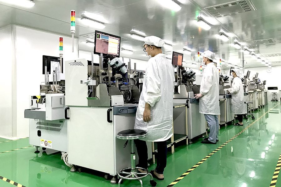
For B2B buyers, tier-1 suppliers, and vehicle OEMs, procurement is not merely about purchasing a component; it is about establishing a reliable development partnership. CAS provides structured support throughout the product lifecycle, from initial optical design and thermal simulation to toolmaking, photometric verification, and mass production.
By maintaining rigorous quality management systems, CAS ensures that every daytime running light manufactured meets the demanding durability requirements of the commercial automotive sector. Our engineering teams work directly with client specifications to integrate custom mounting, aesthetic signatures, and wiring interfaces, reducing lead times and ensuring seamless integration into the vehicle assembly line.
Frequently Asked Questions
Q1: What is the main difference in regulatory compliance between ECE R87 and FMVSS 108 for daytime running lamps?
A1: ECE R87 is a dedicated European regulation specifying precise luminous intensity ranges (400 to 1200 cd) and strict distribution angles specifically for daytime running lamps. In contrast, North American FMVSS 108 allows more flexibility, including the use of dimmed high-beam headlamps, turn signals, or dedicated lamps for daytime running functionality, each with differing intensity and placement parameters.
Q2: Why do LED daytime running lights require active or passive thermal management if LEDs do not emit heat in the light beam?
A2: While LEDs do not emit infrared radiation (heat) forward in the light beam like halogen bulbs, they generate substantial heat at the semiconductor junction on the backside of the diode. If this heat is not removed through passive conduction via MCPCBs and aluminum heat sinks, the junction temperature will rise, causing accelerated lumen depreciation, color shifting, and eventual driver failure.
Q3: How does a dual-function daytime running light dim to become a position light at night?
A3: This is achieved through the LED driver circuitry, which typically uses pulse-width modulation (PWM) or analog current reduction. When the headlamps are switched on, a control signal tells the driver to reduce the duty cycle or the current flowing to the LEDs, safely lowering the light output to position-light levels (typically 4 to 140 cd) to prevent blinding oncoming drivers at night.
Q4: Why is a breathable vent necessary in a sealed IP67 or IP69K daytime running light housing?
A4: When the lamp is turned on, internal temperatures rise, causing the air inside the sealed housing to expand and increase pressure. When turned off, the lamp cools, creating a partial vacuum. Without a semi-permeable membrane vent (which allows air molecules but not water molecules to pass), these pressure fluctuations would eventually fatigue and rupture the housing seals, leading to moisture ingress and fogging.
Q5: What mechanical test standards are used to ensure daytime running lights survive on heavy-duty trucks?
A5: Commercial-grade lights undergo extensive testing including SAE J575 for vibration and environmental resistance, thermal shock testing (cycling rapidly between extreme cold and heat), salt spray exposure for corrosion testing, and chemical resistance tests to ensure the housing and lens can withstand diesel, oil, and cleaning solvents.
For detailed engineering consultations, photometric data sheets, or customized manufacturing options tailored to your fleet or vehicle manufacturing requirements, please contact the product development team at CAS to submit your inquiry.