Solid-state lighting has transitioned from low-power indication indicators to high-density illumination systems. High-intensity applications, such as automotive headlamps, digital projection engines, and industrial searchlights, demand high optical flux density from compact source areas. When blue laser diodes or high-power LED arrays pump energy into phosphor materials to generate white light, the localized energy density rises significantly. This concentrated excitation leads to severe thermal challenges at the wavelength conversion layer.
Conventional packaging configurations, where phosphor powder is suspended in organic silicone matrices directly on the semiconductor junction, often fail under intense blue light irradiance. The organic binders suffer from irreversible thermal-oxidative yellowing, which reduces transmission and causes a permanent drop in luminous efficacy. To resolve this physical limitation, secondary optical and thermal designs are required. The development of a remote shield phosphor plate offers a practical alternative, separating the optical conversion material from the primary semiconductor heat source while providing an independent thermal dissipation path. CAS works with lighting designers to manufacture high-durability inorganic conversion components that maintain spectral consistency under demanding operational conditions.
The Physics of Heat Generation and Spectral Degradation in Phosphor Systems
The primary mechanism of light generation in phosphor-converted white light systems involves down-conversion. A high-energy blue photon (typically around 450 nanometers) is absorbed by the phosphor host lattice and re-emitted as a lower-energy photon (such as yellow-green light). The difference in energy between the absorbed photon and the emitted photon is lost as heat through lattice vibrations, a process known as Stokes shift loss. In high-power applications, this Stokes loss accounts for approximately 25% to 30% of the total incident optical power. If this heat is not removed from the converting medium, the temperature of the phosphor rises rapidly.
As the temperature of the converting crystal increases, the probability of non-radiative relaxation pathways within the active dopant ions, such as trivalent cerium (Ce3+), increases. This phenomenon, known as thermal quenching, causes a decline in internal quantum efficiency. The light output drops as the temperature rises, resulting in a non-linear relationship between excitation power and emitted light. The spectral distribution also shifts, usually causing a blue-shift or yellow-shift in the overall light output, which affects the correlated color temperature (CCT) and color rendering index (CRI) of the lighting system.
Beyond thermal quenching, optical scattering within the converting layer presents a major challenge. When light is backscattered toward the excitation source instead of being directed forward, it is often absorbed by the reflective packaging components or the semiconductor chip itself. This backscattering reduces the overall package efficiency and increases thermal loading. Managing this backscattered light while maintaining a path for heat extraction is a central focus of modern solid-state light engine design.
Architectural Breakdown of the Shield Phosphor Plate
A shield phosphor plate is designed to separate the heat-generating converter layer from the heat-sensitive semiconductor junction. Rather than using an organic polymer matrix, these plates rely on inorganic materials and specialized layering to handle high heat flux. The construction typically involves three functional zones:
The Transmitting or Reflective Substrate: The base material must possess high thermal conductivity and excellent optical properties. Common choices include sapphire, single-crystal alumina, or high-purity ceramic substrates. Sapphire provides thermal conductivity of around 35 to 40 W/m·K, which is far superior to standard glass or silicone. Depending on the optical layout, this substrate can be transparent (for transmissive designs) or highly reflective (for reflective designs).
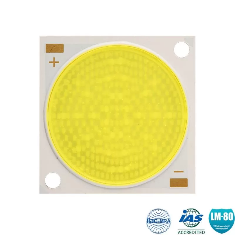
The Luminescent Converter Layer: This layer consists of a fully inorganic matrix, such as a co-precipitated ceramic phosphor plate or a thin-film phosphor deposited onto the substrate. Free of organic silicones, this layer can withstand operating temperatures exceeding 200°C without undergoing browning or structural degradation.
The Interface and Shielding Layer: Situated between the phosphor and the optical components, this layer controls light direction and acts as a barrier against atmospheric moisture and oxidation. It may also include dielectric coatings that selectively reflect blue excitation light while transmitting converted yellow light, reducing the amount of backscattered light that reaches the pump source.
By using a shield phosphor plate, engineers can decouple the optical excitation area from the heat dissipation path. The phosphor layer is physically bonded to a metal or ceramic frame that acts as a heat sink, ensuring the conversion zone remains cool even under high excitation density. CAS provides specialized mounting interfaces and material combinations to ensure that thermal resistance between the phosphor plate and the housing is minimized.
Evaluating Thermal Dissipation in Transmissive vs. Reflective Configurations
When implementing a shield phosphor plate, system designers must choose between two optical architectures: transmissive and reflective. Both approaches have distinct thermal and optical properties that influence overall system design.
In a transmissive configuration, the blue excitation light hits one side of the plate, and the converted white light is collected from the opposite side. While this allows for straightforward, inline optical designs, it presents thermal challenges. The heat must travel through the thickness of the phosphor plate to reach the edges where the plate is mounted to the metal frame. Because the center of the plate is far from the heat sink, it tends to develop a hot spot, limiting the maximum excitation density the system can handle.
In contrast, the reflective configuration places the phosphor layer in direct contact with a highly reflective, thermally conductive substrate, such as a copper or aluminum heat sink with a high-reflectivity dielectric coating. The blue excitation light strikes the phosphor layer from the front, and the converted light, along with reflected blue light, is collected from the same side. Because the entire back surface of the phosphor plate is in direct contact with a metal heat sink, the thermal resistance is significantly lower. This setup allows for much higher excitation densities, making reflective configurations the standard for laser-activated remote phosphor searchlights and automotive projectors.
Application Scenarios of Shield Phosphor Plate Systems
High-power lighting applications require stable light output over thousands of hours in harsh environments. The use of a shield phosphor plate helps meet these demanding reliability requirements.
Automotive Laser Headlamps
Modern passenger vehicles use laser-based high-beam modules to achieve illumination distances of over 600 meters. These systems use blue laser diodes focused onto a small phosphor target to create an extremely bright, point-like light source. By using a reflective shield phosphor plate, automotive engineers can achieve high luminance while keeping the optical source small enough to fit within compact, aerodynamic headlamp housings.
Digital Cinema and Stage Projection
High-lumen projectors require intense white light to illuminate large screens. Traditional high-pressure mercury lamps have short lifespans and contain hazardous materials. Laser-phosphor light engines offer a more reliable alternative, using a rotating wheel or a static shield phosphor plate to convert blue laser light. The static plate configuration is preferred for compact, low-noise projectors because it eliminates mechanical wear and vibration.
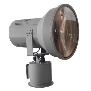
Searchlights and Marine Signaling
Searchlights used for search and rescue, border security, and maritime navigation must produce narrow, high-intensity beams that can penetrate fog and long distances. These systems rely on high excitation densities to maximize the center-beam candlepower. Utilizing a durable conversion plate prevents thermal degradation during continuous operation in high-humidity, high-saline marine environments.
Engineering Specifications for Integration and Manufacturing
Successfully integrating a shield phosphor plate into an optical assembly requires precise matching of physical and optical properties. System designers must evaluate several key factors during the design phase:
Coefficient of Thermal Expansion (CTE) Matching: The phosphor layer and the substrate must have closely matched CTE values. Significant differences in CTE can lead to thermal stress during temperature cycles, causing the phosphor layer to delaminate from the substrate.
Surface Roughness and Interface Quality: The surface of both the substrate and the phosphor layer must be polished to minimize optical scattering at the interface. High surface roughness can trap light within the plate through total internal reflection, increasing absorption losses and thermal loading.
Excitation Density Limits: Designers must calculate the thermal dissipation capacity to ensure the phosphor does not exceed its thermal quenching temperature. For typical ceramic phosphors, this limit is around 15 to 25 W/mm² of blue laser power, depending on the effectiveness of the cooling system.
CAS employs specialized material processing and precision bonding techniques to ensure that each shield phosphor plate meets strict dimensional and thermal tolerances. This careful manufacturing process helps minimize batch-to-batch variation, ensuring consistent color temperature and luminous output across production runs.
Frequently Asked Questions
Q1: What is the main structural difference between a standard phosphor wheel and a static shield phosphor plate?
A1: A phosphor wheel uses rotation to spread the heat of a laser beam over a larger surface area, allowing it to handle higher excitation power. A static shield phosphor plate remains stationary and relies entirely on high thermal conductivity materials (such as sapphire or copper substrates) to conduct heat away from the excitation spot. This static design eliminates mechanical motors, reduces system noise, and increases physical reliability.
Q2: Why is silicone browning not an issue with this type of phosphor plate?
A2: The shield phosphor plate uses a fully inorganic design, replacing organic silicone binders with ceramic matrices, glass-phosphor composites, or thin-film depositions. Because there are no carbon-based polymers present, there is no organic material to undergo thermal oxidation or UV-induced yellowing, even when exposed to intense blue light and high operating temperatures.
Q3: How does the thickness of the phosphor layer affect optical performance?
A3: The thickness of the phosphor layer determines the balance between blue light absorption and yellow light emission. If the layer is too thin, excessive blue light passes through, resulting in a high CCT (cool, bluish-white light). If the layer is too thick, internal scattering and re-absorption increase, which lowers the optical efficiency and raises the operating temperature of the plate. Optimizing this thickness is key to achieving the desired chromaticity coordinates.
Q4: Can these plates be used with multi-wavelength LED arrays?
A4: Yes, a shield phosphor plate can be used in remote phosphor configurations with multi-wavelength LED arrays. This setup helps mix the light from different LED dies, such as blue, red, and green, resulting in a more uniform color distribution and reducing the pixelation effect often seen in direct-emission multi-chip LED modules.
Q5: What cooling methods are recommended for high-power laser-activated configurations?
A5: For laser excitation powers below 10 watts, passive cooling using high-surface-area aluminum heat sinks with natural convection is usually sufficient. For higher powers, active cooling methods, such as forced air convection, liquid cooling blocks, or thermoelectric coolers (TECs) mounted directly to the substrate holder, are recommended to keep the phosphor temperature below its thermal quenching threshold.
Commercial Inquiry and Partnership
Selecting and integrating the right optical conversion components is key to building reliable, high-performance solid-state lighting systems. CAS provides design assistance, custom manufacturing, and material testing services to help you match our shield phosphor plate designs with your specific thermal and optical requirements. If you are developing next-generation automotive headlamps, high-lumen projectors, or industrial searchlights, contact our engineering team to discuss your project specifications and request a technical consultation.