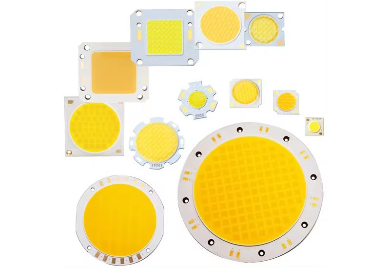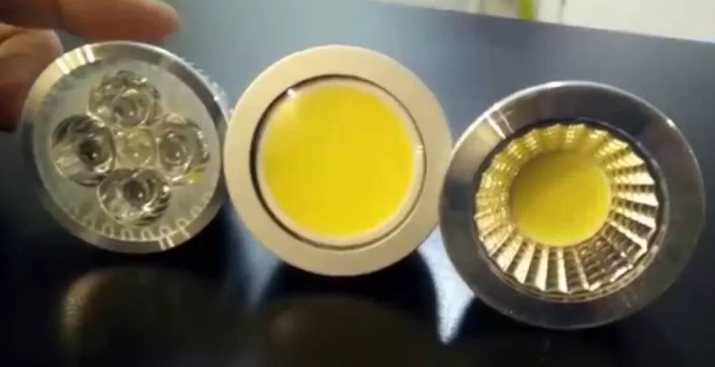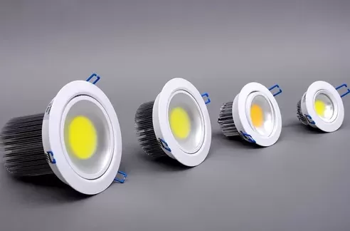
Modern vehicular cockpits rely heavily on spatial projection interfaces to display navigation vectors, velocity metrics, and advanced driver-assistance alerts directly within the driver's forward field of view. The architectural core of any automotive Head up display centers on the Picture Generation Unit (PGU). Within this unit, the solid-state light source determines visual clarity, operational longevity, and legibility across dynamic ambient light environments. Achieving seamless visual projection demands precise control over optical efficiency, thermal dissipation, and beam collimation. Optical components developed by CAS address these structural challenges, delivering steady luminance and color stability under demanding operational conditions.
Photometric Demands and Ambient Light Interference
Direct sunlight striking a vehicular windshield creates high ambient illumination that easily obscures projected graphics. Under worst-case scenarios, ambient daylight intensity can reach up to 100,000 lux. To ensure projected warnings remain legible, the optical light engine within a Head up display must generate peak luminance levels ranging between 10,000 and 15,000 cd/m² at the display source plane.
Designing illumination systems for these high-contrast environments introduces distinct physical requirements:
Luminance Contrast Ratio: To maintain clear visual separation against high-reflectance background surfaces like snow or light concrete, the system requires an optical contrast ratio exceeding 10:1. This is achieved by pairing narrow spectral distribution LED dies with precise spatial illumination masks.
Sunload Thermal Exposure: Solar energy passing back through the projection optics acts like a magnifying element, focusing concentrated thermal flux directly onto the light engine. Components situated near the optical image plane must resist localized thermal spikes without mechanical warping or chromaticity shifts.
Spatial Luminance Uniformity: Uneven light distribution across the active projection field causes driver distraction. Target optical specifications mandate spatial uniformity values above 90% across the full field of view.
Core Projection Light Source Architectures
Selecting the optimal solid-state illumination architecture depends on the specific display technology employed within the primary picture generation unit. Three dominant light engine configurations currently define the industry standard.
Thin-Film Transistor (TFT) Matrix Backlighting
TFT-LCD based engines remain widespread due to mature manufacturing ecosystems and cost-effective scaling. However, traditional edge-lit backlights struggle to deliver the high brightness required for advanced projection applications. Modern implementations utilize direct-lit matrix LED arrays operating with local dimming capabilities. By dynamically lowering backlight brightness in inactive pixel zones, local dimming eliminates residual light bleed—commonly referred to as the postcard effect—during low-ambient nighttime operation.
Digital Light Processing (DLP) Illumination
DLP projection systems rely on high-power RGB LED clusters configured to illuminate a micro-mirror spatial light modulator. Because DLP chips reflect rather than absorb light, overall optical throughput remains higher compared to transmissive LCD systems. The primary design objective involves condensing high luminous flux into a small optical etendue, requiring custom collimation optics and precise mechanical alignment of individual red, green, and blue solid-state emitters.
Micro-LED Direct-Emissive Arrays
Direct-emissive Micro-LED technology represents a significant architectural evolution for next-generation display design. By eliminating secondary backlight panels, polarization filters, and liquid crystal layers, Micro-LED matrices project light directly from self-emissive microscopic diode pixels. This streamlined optical path offers higher wall-plug efficiency, reduced packaging volume, and near-instantaneous response times, making it ideal for compact dash integration where space is restricted.
Thermal Engineering and Optical Efficiency in Picture Generation Units
Operating LED emitters at maximum drive currents within sealed dashboard enclosures generates substantial internal heat. Continuous operation at elevated junction temperatures accelerates lumen depreciation and shifts the dominant emission wavelength, causing undesirable color variations in projected graphics. Thermal management strategies must be integrated directly into the substrate and optical assembly level.
Addressing thermal resistance requires direct-bonded copper (DBC) or ceramic substrates rather than standard FR4 printed circuit boards. Ceramic materials provide superior dielectric strength while conducting thermal energy away from the diode junction toward passive heat sinks or active thermal management circuits. Controlling junction temperature stabilizes output flux and prolongs the operational lifespan of the entire illumination module.
In parallel with heat dissipation, optical path optimization minimizes internal attenuation loss. Unwanted light reflections inside the optical housing generate stray light artifacts and reduce image contrast. Precision beam-shaping lenses and customized total internal reflection (TIR) optics gather wide-angle emissions from the LED chips, homogenizing the output profile before it impinges on the spatial light modulator. Controlling emission angles ensures maximum light transport efficiency through windshield interlayers, reducing optical ghosting and phantom images.
Custom Illumination Modules Designed by CAS
Meeting the strict environmental and photometric demands of automotive OEMs requires specialized light source engineering. CAS develops customized LED arrays, light guides, and driver control circuitry specifically optimized for integration into modern Head up display configurations.
Engineered to meet automotive reliability specifications, CAS illumination components focus on three critical design factors:
Targeted Spectral Binning: Tight color binning parameters ensure precise chromatic consistency across operating temperature spectrums, matching strict automotive color standards.
High-Density Matrix Packaging: Custom surface-mount configurations minimize diode pitch, yielding higher flux density per square millimeter while optimizing thermal dissipation routes.
Integrated Monitoring Diagnostics: Built-in thermistors and photodiodes provide continuous real-time feedback to drive electronics, enabling dynamic drive current adjustments to preserve color balance and brightness levels.
Photometric and Mechanical Architecture Comparison
The table below summarizes key operational parameters across standard light source configurations integrated within modern projection displays:
| Light Source Configuration | Peak Luminance Potential | Thermal Resistance (K/W) | Dynamic Contrast Ratio | Mechanical Package Volume |
|---|---|---|---|---|
| Direct-Lit TFT Matrix (LED) | 10,000 – 12,000 nits | 1.8 – 2.5 | 10,000:1 (Local Dimming) | Moderate |
| High-Power RGB LED (DLP) | 12,000 – 15,000 nits | 1.2 – 1.8 | 5,000:1 | Large |
| Micro-LED Array (Direct Emissive) | 15,000+ nits | 0.8 – 1.2 | 100,000:1 (Pixel-level) | Compact |
Optical Integration and Industrial Supply Calibration
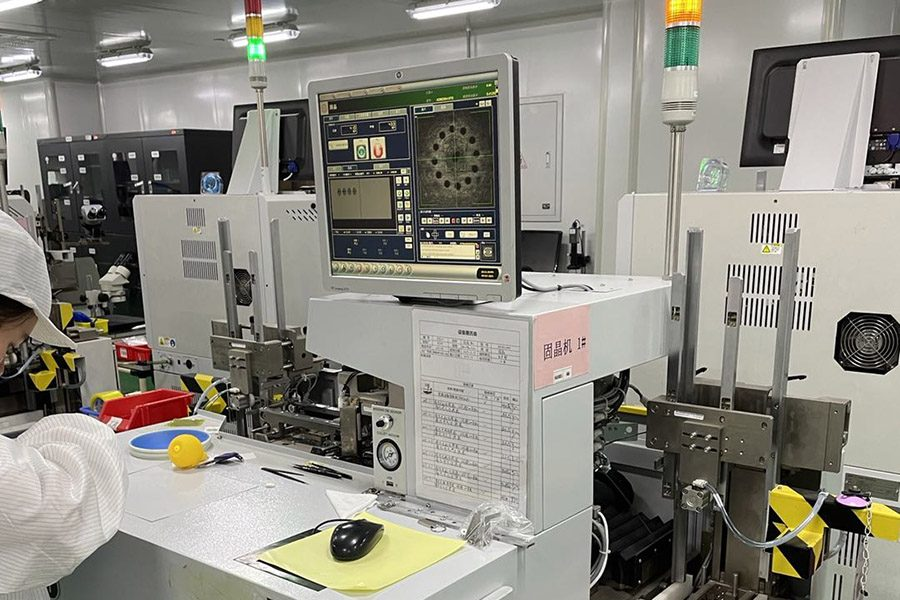
Transitioning from optical simulations to commercial manufacturing requires rigorous quality control and strict component tolerances. Automotive tier-one suppliers require optical modules that maintain physical alignment despite persistent vehicle vibrations, thermal cycling ranging from -40°C to +105°C, and high relative humidity levels.
Early collaboration during the optical design phase ensures that mechanical enclosures, board layout geometry, and thermal interfaces align with the physical constraints of specific vehicle cockpits. Standardized photometric testing, including goniophotometric emission mapping and automated optical inspection, validates component compliance before final assembly integration.
Submit your optical specification sheets, mechanical dimensions, and photometric target requirements directly to the CAS technical team to receive detailed component simulations, custom matrix configurations, and evaluation prototypes for upcoming vehicle platform designs.
Frequently Asked Questions
Q1: What luminous output is necessary for an automotive Head up display to remain visible under bright daylight?
A1: Light engines inside a projection unit typically need to output between 10,000 and 15,000 cd/m² (nits) of direct luminance. This ensures that the projected image maintains a clear visual contrast ratio of at least 10:1 against ambient road surfaces illuminated by intense solar radiation up to 100,000 lux.
Q2: How does sunload affect the optical components inside a projection module?
A2: Sunload occurs when ambient sunlight passes backward through the windshield combiner optics, acting as a magnifying lens that focuses high thermal energy directly onto the internal light engine plane. Light source modules require high-temperature ceramic substrates, thermal barrier coatings, and heat sink structures to prevent component warping and chromatic degradation.
Q3: Why is matrix local dimming valuable in display backlighting?
A3: Matrix local dimming allows individual sectors of an LED backlight array to dim or turn off completely in dark sections of a frame while maintaining high brightness in active pixel areas. This high dynamic range prevents light leakage, suppressing the faint background box artifact visible during nighttime operation.
Q4: How do Micro-LED light engines compare to conventional backlit LCD architectures?
A4: Micro-LED structures use self-emissive micro-scale diodes, bypassing the need for backlights, liquid crystal layers, and spatial polarization filters. This structural simplification delivers higher light transmission efficiency, faster response times, reduced thermal overhead, and a smaller overall package size.
Q5: What role does polarization play in head up display projection paths?
A5: Precise polarization alignment controls how light rays reflect off the inner and outer surfaces of windshield glass interlayers. Managing light wave polarization suppresses dual-reflection visual artifacts—commonly known as ghosting—ensuring a clean, single projected image reaches the driver.