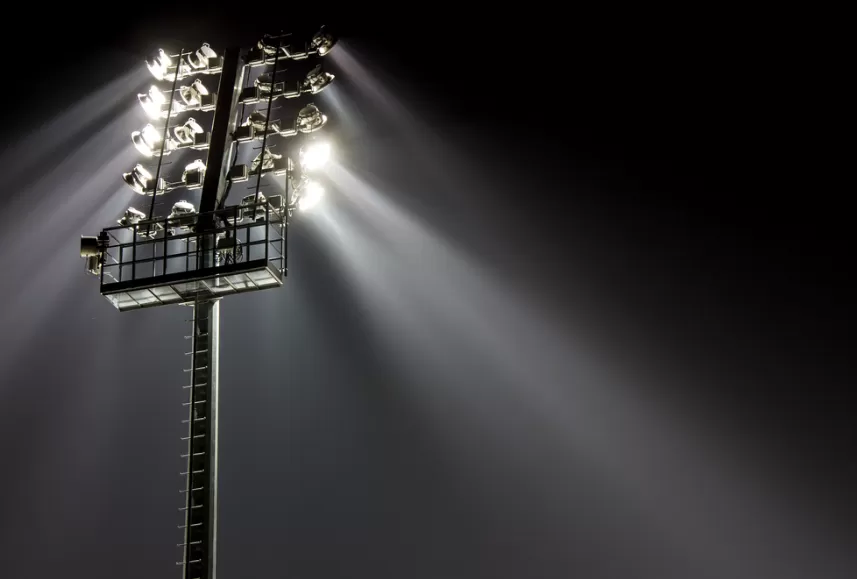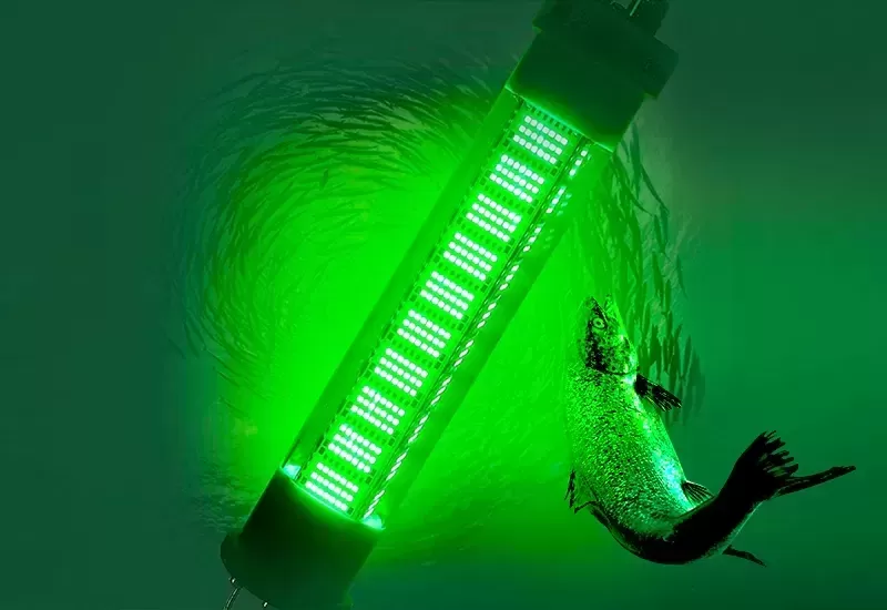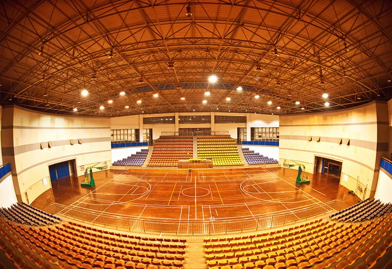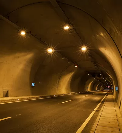
High-mast installations, sports arenas, and film production sets demand massive lumen packages from compact fixtures. For decades, legacy systems relied on 1000W to 1500W metal halide lamps. These legacy systems wasted substantial energy as stray heat and required bulky optical housing.
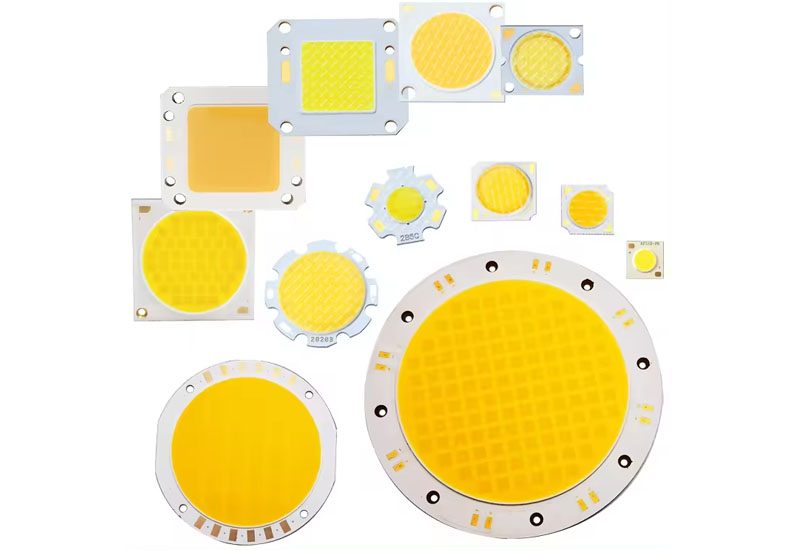
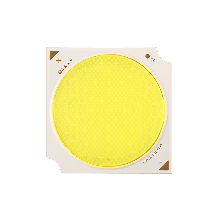
The modern solid-state lighting sector handles this challenge with a single component: the Led Cob 500w module. By concentrating hundreds of microscopic light-emitting diodes onto a surface the size of a credit card, these high-density engines alter luminaire engineering.
At CAS, we manufacture and deploy ultra-high-power light sources for industrial fixtures. Understanding how a 500-watt chip-on-board assembly balances photon output with thermal stress allows fixture engineers to design smaller, longer-lasting, and optically superior luminaires.
Anatomy of a 500W COB: Micro-Scale Architecture
Generating tens of thousands of lumens from a compact surface requires precision micro-packaging. A standard 500W COB module integrates anywhere from 400 to over 1,000 discrete semiconductor dies onto a single thermally conductive plane.
Flip-Chip vs. Traditional Wire-Bonded Dies
Older high-power COBs relied on horizontal wire-bonded chips. In this setup, delicate gold wires carried electrical current to the top of each die. However, these wires introduce structural vulnerability and obstruct the primary light extraction path.
Advanced 500W modules now favor flip-chip packaging. In this design:
The chip mounts upside down directly on the substrate pads.
Electrical contacts bond straight to the underlying circuit via eutectic solder or gold-tin (AuSn) pastes.
Eliminating gold bonding wires removes a common failure point caused by thermal expansion and thermal fatigue.
Light emits through the top transparent sapphire or silicon carbide layer without shadow-casting wires.
Substrate Engineering: Aluminum Nitride (AlN) and DPC
A conventional aluminum metal-core printed circuit board (MCPCB) works adequately at 50 watts. At 500 watts, it quickly causes thermal throttling. Standard dielectric layers within MCPCBs exhibit poor thermal conductivity, typically between 1.0 and 3.0 W/mK.
To prevent catastrophic failure, a modern 500 watt cob led module employs Aluminum Nitride (AlN) ceramic substrates. AlN delivers an exceptional thermal conductivity of 170 to 200 W/mK combined with high dielectric insulation.
Manufacturers integrate Direct Plated Copper (DPC) technology onto the AlN base. DPC utilizes thin-film sputtering to bond copper directly to the ceramic. This yields an ultra-flat surface, exceptional trace accuracy, and superior adhesion under severe thermal cycling.
Phosphor Conversion and Encapsulation Chemistry
Raw blue radiation from InGaN (Indium Gallium Nitride) dies must convert into stable white light. In a concentrated 500W light-emitting surface (LES), the blue light flux density is intense.
Standard packaging resins degrade quickly under this photon bombardment. Premium high power cob led modules utilize high-temperature, optical-grade phenyl silicones. These silicones resist yellowing at operating temperatures exceeding 150°C.
Engineers blend customized garnet (YAG/LuAG) or nitride phosphors directly into the matrix. The phosphor blend must resist thermal quenching—a phenomenon where phosphor quantum efficiency drops as temperatures rise, leading to unwanted chromaticity drift.
Thermal Dynamics: Managing the Heat Path
Physics dictates that LEDs do not convert 100% of electrical energy into visible light. A top-tier Led Cob 500w achieves roughly 35% to 45% wall-plug efficiency. The remaining 55% to 65% converts directly into thermal energy.
This means fixture builders must dissipate approximately 300 to 325 watts of pure heat from a tiny light-emitting area (often between 28mm and 45mm in diameter).
| Layer in Thermal Stack | Material Composition | Thermal Conductivity (W/mK) |
|---|---|---|
| LED Die Epitaxy | InGaN on Sapphire/SiC | ~35 - 120 |
| Die Attach Material | AuSn Eutectic or Sintered Silver | 50 - 250 |
| COB Substrate | Aluminum Nitride (AlN) Ceramic | 170 - 200 |
| Thermal Interface (TIM) | Phase Change Material / Carbon Pad | 4 - 12 |
| Base Heat Sink / Vapor Chamber | Oxygen-Free Copper / Pure Aluminum | 200 - 400 |
Controlling Junction Temperature ($T_j$)
The primary metric governing COB reliability is the junction temperature ($T_j$). Operating a 500W module with a $T_j$ above 85°C significantly shortens working life and degrades lumen maintenance.
The total thermal resistance ($R_{th}$) from the internal junctions down to the ambient air operates like resistors in series. If the thermal interface material (TIM) is uneven or poorly applied, the thermal barrier spikes.
At CAS, our testing laboratories recommend high-conductivity phase-change materials (PCM) or sintered silver interface pastes over standard generic silicon grease for 500W modules. This lowers the contact thermal resistance by up to 40%.
Integration with Vapor Chambers and Heat Pipes
Traditional extruded aluminum heatsinks struggle to pull 300W+ of localized heat away fast enough to prevent center hotspotting. The thermal conduction through solid metal is too slow for extreme watt densities.
Engineers combine 500W COBs with two-phase thermal spreaders:
Vapor Chambers: A sealed planar vacuum chamber with an internal capillary wick. Working fluid evaporates at the COB base, sweeps across the surface, condenses, and returns. This makes the effective thermal conductivity exceed 1,500 W/mK.
Copper Heat Pipe Arrays: Embedded heat pipes redirect concentrated heat outward into broadly spaced aluminum cooling fins cooled by natural convection or low-noise active fans.
Electrical Drive Characteristics and Optical Control
Operating a high-wattage chip array requires precise electrical matching. A typical 500W COB does not run on a low-voltage rail; it uses a matrix of series-parallel circuits.
Voltage and Current Topologies
Most 500W platforms run on configurations yielding a forward voltage ($V_f$) between 50V and 75V, paired with drive currents ranging from 6.5A to over 10A.
Matching the driver requires strict attention to:
Forward Voltage Tolerances: Cold-start conditions exhibit higher $V_f$ than running temperatures. The constant current driver must provide adequate voltage overhead.
Inrush Current Mitigation: High-amperage systems require integrated soft-start circuits to protect the multi-die matrix from voltage overshoot.
Surge Suppression: Industrial power rails experience transient spikes. Drivers paired with the 500W COB need minimum 6kV to 10kV line-to-line surge protection ratings.
Secondary Optics: Maximizing Center Beam Candlepower (CBCP)
A major disadvantage of large Surface Mount Device (SMD) arrays is optical scattering. Trying to focus hundreds of distinct SMD packages into a tight 10-degree beam requires complex, bulky arrays of individual lenses. This introduces optical losses and multiple overlapping edge shadows.
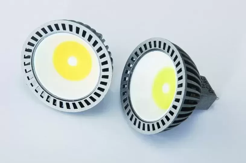
A Led Cob 500w acts as a concentrated quasi-point source. Fixture designers can position a single metal reflector or high-grade silicone collimating lens over the module.
This single-source geometry yields:
Crisp, sharp shadows without the disorienting "multi-shadow" effect.
Exceptionally high center beam candlepower (CBCP) for long throw distances.
Narrow beam angles (sub-15 degrees) using clean, compact reflectors.
Smaller luminaire housing footprints, reducing wind load profiles on high masts.
Critical Industrial and Commercial Applications
Where does a single high-output 500W emitter outshine distributed SMD arrays or traditional discharge lamps?
Stadium and Arena Lighting
Modern sports venues broadcast in 4K and high-speed slow-motion (8K/1,000+ fps). This environment requires lights with zero perceptible flicker. When paired with high-frequency ripple-free drivers, the 500W COB provides smooth, deep-well illumination that meets rigorous broadcast TLCI criteria.
High-Mast Commercial Infrastructure
Container ports, railway yards, and airport aprons require continuous light over expansive footprints. Servicing fixtures 30 meters up is costly and disruptive. The high reliability and unified optical control of a 500W COB reduce both physical luminaire weight and periodic service trips.
Studio, Film, and Entertainment Work
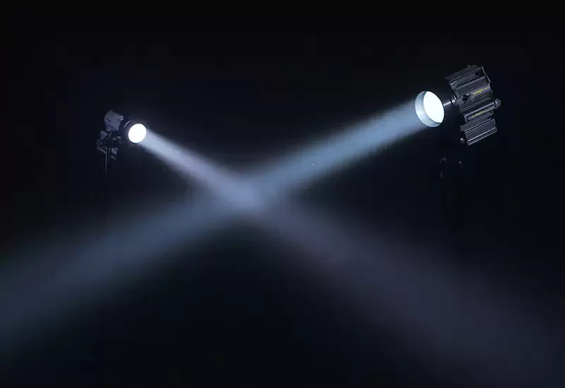
Cinematographers require massive output that can balance bright midday sunlight. High CRI cob 500w engines offer CRI ratings above 97 and TLCI ratings over 98. This enables hard-source focusing through Fresnel lenses or smooth diffusion through large softboxes.
Buyer's Evaluation Checklist: Qualifying 500W COB Modules
Procuring high-wattage components for OEM fixture lines requires careful supply-chain auditing. Inadequate thermal builds often function for a few hundred hours before experiencing severe lumen decay.
LM-80 / TM-21 Reports: Request third-party test data validated at high case temperatures ($T_s = 85^\circ\text{C}$ and $105^\circ\text{C}$). Never accept data conducted purely at low currents.
Substrate Verification: Confirm that the module uses genuine Aluminum Nitride (AlN) with Direct Plated Copper rather than standard Alumina ($Al_2O_3$) or low-grade MCPCB.
Color Consistency (MacAdam Ellipse): Ensure your supplier provides 3-step or 2-step MacAdam ellipse binning to prevent visible color variations between side-by-side luminaires.
Transient Protection: Check whether the COB substrate incorporates bi-directional TVS (Transient Voltage Suppressor) diodes directly into the circuit to guard against ESD damage.
Frequently Asked Questions (FAQ)
Q1: What is the typical lumen output of a commercial Led Cob
500w?
A1: A standard 500W COB operating at 130 to 160 lumens per
watt outputs between 65,000 and 80,000 lumens. High-CRI versions (95+ Ra)
typically produce slightly lower yields (around 55,000 to 65,000 lumens) due to
heavier phosphor absorption across red wavelengths.
Q2: How large does a heatsink need to be for a 500-watt
COB?
A2: For passive cooling, an aluminum fin heatsink typically
requires a substantial surface area, often exceeding 12,000 to 15,000 square
centimeters, weighing 8 to 14 kilograms. If utilizing active cooling (pin-fin
heat sinks with industrial pulse-width modulated blowers) or vapor chambers, the
physical footprint can drop by over 60%.
Q3: Can I run a 500W COB on a standard off-the-shelf LED
driver?
A3: Yes, provided the driver's constant-current range
matches the COB's forward voltage ($V_f$) and current parameters. Most 500W
modules operate best with specialized constant-current industrial drivers
providing 50V-70V at 7A-10A. Always verify that driver surge protection and
thermal foldback features match the module limits.
Q4: Why pick a single 500W COB over an array of 500 1-watt SMD
LEDs?
A4: Optical control and fixture dimensions dictate this
choice. SMD arrays spread light over a broad surface area, making narrow-beam
focus difficult without complex, heavy multi-lens optics. A 500W COB
concentrates emission into a single point source, enabling compact optics,
long-distance projection, zero multi-shadowing, and simplified fixture
maintenance.
Q5: What causes a 500W COB to burn out prematurely?
A5:
Inadequate thermal dissipation is the primary cause of failure. Insufficient
heat sink sizing, uneven thermal interface material application, or operating
past maximum junction temperature limits leads to rapid phosphor discoloration,
die solder fatigue, bond degradation, and localized thermal runaway.
Build Your High-Power Fixtures with CAS
Designing high-output luminaires demands high-grade components that survive rigorous environmental conditions. CAS supplies robust, field-tested Led Cob 500w light modules, customized drivers, and optimized thermal solutions built to your OEM/ODM mechanical requirements.
Contact our engineering sales team today to discuss your project specifications, request photometric IES files, or receive your initial qualification samples.